PipeMetric Pro training
Learn the field workflow
Eight illustrated lessons, a worked cut-length example and a crew handoff checklist.
Version 1.0. Screenshots show the simulator interface; verify real measurements independently.
Contents
- Start a practice project
- Read the reference and its limits
- Calculate a cut and show the work
- Use Check My Work
- Review the drawing and export a report
- Enter or import your company tables
- Review a photographed or PDF table
- Calibrate and verify field measurements
Lesson 1
Start a practice project
Use a practice project to learn the workflow before entering a live job. PipeMetric works on the device without an account; sharing a report is a separate action you choose.
- Open Projects, create a project, then add a spool. Give the spool a name that will make sense in the handoff.
- Choose the material, connection system, nominal size and applicable schedule or class. Add fittings and pipe runs.
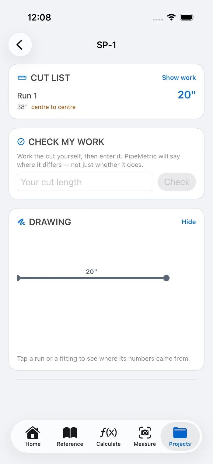
- Enter the measured gross dimension and confirm what its endpoints mean. Centre-to-centre and end-to-end are different inputs.
- Use Calculate for standalone field math and Reference for the available dimensional tables. Home search can help find a tool.
Before calculating, identify the size, system, units, dimension endpoints and job-specific allowances. Example projects are practice data, not job instructions.
Lesson 2
Read the reference and its limits
A nominal size is a selection label, not a measurement of every physical diameter. Match the selected product and connection system before using a reference value.
- Open Reference and select the relevant pipe, fitting or flange family. Choose the nominal size and schedule or pressure class.
- Read the source, revision and coverage notes. A missing combination is a gap; do not substitute another maker's dimensions.
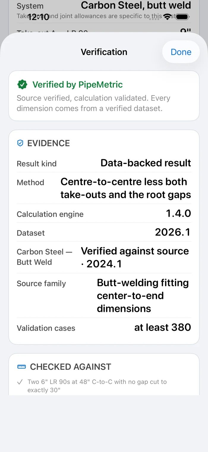
- Open Verification when offered on a result. Review the method, dataset and assumptions rather than relying on a badge alone.
- For flange thickness, read whether the raised face is included. Class 150/300 stored minimum thickness includes it; Class 600 adds it. Stud lengths are calculated estimates to confirm against the job specification.
The current build separates 20- and 22-inch Schedule 10S walls (0.218 in) from Schedule 10 (0.250 in). Always use the selected schedule and actual product documentation.
Lesson 3
Calculate a cut and show the work
The useful result is the cut length together with the assumptions that produced it. Read the working before marking a piece of pipe.
- Add the fittings on both ends of the run. Confirm the correct take-out for each fitting and connection system.
- Enter the gross dimension and set the dimension convention. Enter the root gap or other allowances required by the job.
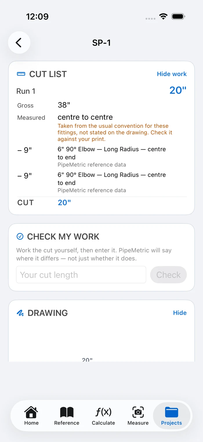
- Tap Show work in the cut list. Check the gross length, each deduction, its source and the final cut.
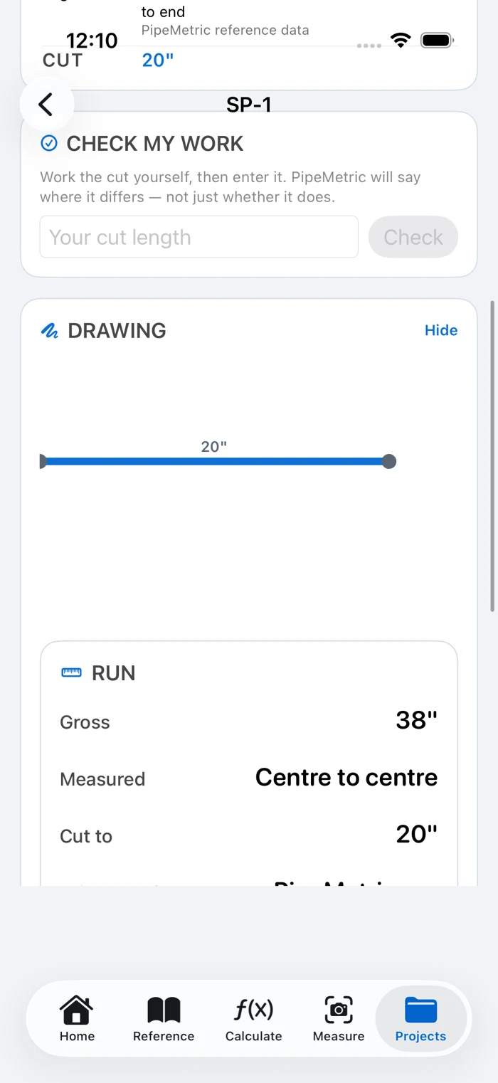
- Practice with a 38-inch centre-to-centre run and two 6-inch long-radius 90-degree elbows. With 9-inch take-outs at both ends and zero gaps: 38 - 9 - 9 = 20 inches.
For the same practice run with two 1/8-inch root gaps, the arithmetic is 38 - 9 - 9 - 1/8 - 1/8 = 19 3/4 inches. This is an exercise; use the allowances on your job.
Lesson 4
Use Check My Work
Work the cut independently, then compare it with the app. A disagreement is a prompt to inspect the setup, not a reason to average the answers.
- Calculate the practice cut by hand and enter your answer in Check My Work.
- Read the explanation of the difference. It may point to endpoint conventions, fitting deductions or gap allowances.
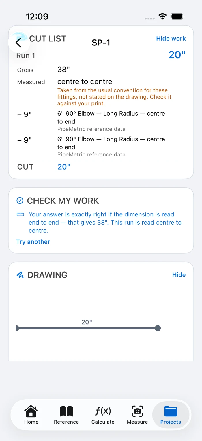
- In the example, entering 38 inches corresponds to an end-to-end reading; the spool is configured centre to centre and gives 20 inches.
- Return to the gross dimension and fitting setup. Correct the assumption that disagrees with the drawing, then check again.
For the zero-gap practice run, the independent answer is 20 inches. Before cutting, confirm both the calculation and the real dimensions against the print and suitable measuring tools.
Lesson 5
Review the drawing and export a report
Projects collect the work so another person can understand the result. A drawing or a shared file does not replace review of the job's drawing and dimensions.
- Open the spool drawing. Check run labels, fittings and dimensions against the intended arrangement.
- Review the project's saved calculations, measurements and notes before exporting.
- Use the project's PDF or CSV export/share action. PDF supports a readable field handoff; CSV supports spreadsheet review.
- Open the exported file and verify the project identity, values, units and source information. Share it only with the intended recipients.
Keep private job information out of practice files. A report can include the dimensions used in a project; obtain any required authorization before redistributing company or supplier material.
Lesson 6
Enter or import your company tables
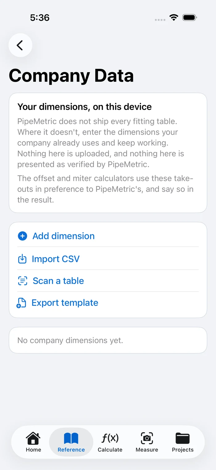
Company Data lets you use the dimensions your organization already works from. These entries remain identified as your data and can take precedence in supported offset and miter calculations.
- Open Reference > Company Data. Choose Add dimension for one entry, or Export template to prepare a spreadsheet.
- Record the material, connection, fitting type, nominal size, designation, manufacturer and source/revision. Fill in the dimensions the selected system requires.
- For manual entry, use decimal numeric values in the fields and confirm their units. Socket work needs both centre-to-end and socket depth.
- For a spreadsheet, follow the exported template, then choose Import CSV, select or paste the file, name the source and tap Check rows. Review held rows before putting them into service.
Check that the result names the intended company source. Do not merge makers or use a company entry as if PipeMetric independently verified it. Resolve conflicts against the actual source.
Lesson 7
Review a photographed or PDF table
A scan proposes values for review. Fractions, faint print, skewed pages and complex grids can be read incorrectly. Every accepted row needs a check against the source.
- Open Company Data > Scan a table. Enter what the table contains and where it came from. Use a straight, close photograph or the available PDF/file option.
- If the reading is poor, choose Crop or straighten this table. Align its four corners; use the grid option only for a regular table. A clearer image may still be necessary.
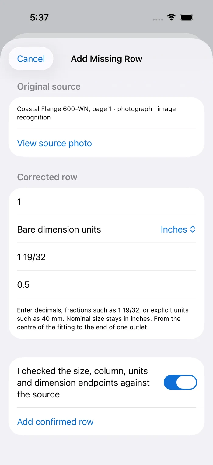
- Confirm dimension units and column meanings. Nominal-size labels remain in inches. Use Correct this row or Add a missing row for omissions or wrong fractions.
- Enter the corrected value, such as 1 19/32 or an explicit value such as 40 mm. View the source, confirm size, column, units and endpoints, then add the confirmed row.
The pictured row is an illustrative review example, not a recommendation for a fitting. If the source or interpretation is unclear, leave the row unaccepted and use manual entry after resolving it.
Lesson 8
Calibrate and verify field measurements
Phone measurements are field estimates. Calibration can correct a repeatable scale/offset bias, but it cannot remove tracking errors or establish accuracy under every site condition.
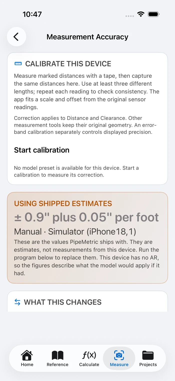
- On a supported physical device, open Measure > Calibrate this device and choose Start calibration.
- Mark at least three different distances and measure them with a suitable tape or reference instrument. Capture the same endpoints in the app and repeat each reading.
- Enter the paired reference and original sensor readings. Review the fit and consistency before applying the correction.
- Check additional distances that were not used to fit the correction. The distance correction applies to Distance and Clearance; other tools retain their original geometry. Error-band calibration separately affects displayed precision.
A model preset is not a calibration of your individual device. Use manual entry when AR is unavailable, and verify anything that will be cut, welded or ordered with an appropriate instrument.
Ready for a handoff
Confirm the project, product family, source/revision, size, units, endpoints and allowances. Inspect the exported file before sharing. Use the final page of the PDF for a practice lab, answer key and trainer checklist.